Vintage Mustang Forums banner
1 - 20 of 22 Posts

INTLgunMonkey

· Registered
Joined
·
355 Posts
Discussion starter · #1 ·
The only gauge that appears to work currently is the temp gauge. The fuel sender is new, and I've checked the resistance on it and the temp and oil pressure senders. All those seem right.

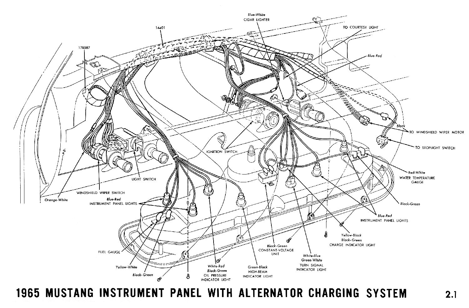
Last night, I puller the dash cluster out and started checking various points. On the CVR, the ground lug shows continuity to other ground points on the car, and I get 12.5 VDC to the ignition lug. I wasn't getting anything on the CVR output lug with my DMM, so I tried an analog one and got signal. It was only showing around 1.5 - 2.5 VDC on the sweep. I think there's some dampening in that MM as well, so I'm thinking the "1.5" should actually be 0, making the "2.5" closer to 4 - still a little lower than I gather it is supposed to be.

My question: do these CVRs ever wear out by giving a low output? My (limited) experience with other CVRs is that they either fail at open or close, not low output.

If it sounds like my CVR is probably OK, I think I'm going to pull the whole cluster and power/resist the individual gauges on a breadboard. Assuming I have + voltage to the + lug on each gauge, and reasonable resistance to ground from each sender wire, if the gauge doesn't work, it has to be a problem with the actual gauge, right?
 
The way I check the instrument voltage regulator is I use my 12 volt test light. I look for a dim @6 volt pulsing voltage. The bulb blinks dimly on and off. You can try this test at the IVR output, and at end of the sender wire at the fuel, temp, and oil pressure switch.
 
The fuel, temp and oil pressure gauges receive their reference voltage from the IVR. Since you have verified that the IVR is properly grounded, using test light touch the probe to the SIGNAL post of each gauge in turn (the post that the sending unit wire attaches) and note the action of each gauge needle. They should move up around 1/3 to 1/2 scale when the test light touches the post.
 
Discussion starter · #4 ·
The way I check the instrument voltage regulator is I use my 12 volt test light. I look for a dim @6 volt pulsing voltage. The bulb blinks dimly on and off. You can try this test at the IVR output, and at end of the sender wire at the fuel, temp, and oil pressure switch.
I didn’t check it with a light, but I’m sure I’d get a flash. The analog meter showed it going from low+ to high(er)+, with about a 1 second frequency.

I’m sure the CVR is alive. I just don’t know if the low VDC reading I was getting were a function of the CVR wearing out or the dampening in my meter.

Unless there’s something else I’m missing, I’m going to pull the whole cluster, pull the gauges, and set up a breadboard with an actual 6VDC supply and a set of three or four 10-82ohm resisters to ground and see if I can get the needles to move. If they don’t, the only thing I can think of is that the gauges actually are bad.

Side question: does anyone know if the instrument lights are wired in series? I have one known bad (broken) bulb, but none of them come on.
 
Discussion starter · #5 ·
The fuel, temp and oil pressure gauges receive their reference voltage from the IVR. Since you have verified that the IVR is properly grounded, using test light touch the probe to the SIGNAL post of each gauge in turn (the post that the sending unit wire attaches) and note the action of each gauge needle. They should move up around 1/3 to 1/2 scale when the test light touches the post.
Yeah- I tried grounding at least the fuel (maybe oil too, I don’t recall) with a jumper and neither did anything.

That’s what had me questioning the CVR output. If, instead of getting 5-6V, the gauges each only got 1-2V (like my meter suggests), would they move at all?
 
Discussion starter · #8 ·
Parallel.
I didn't realize i had that in the schematics. Sorry.

It looks like they're on their own fuse, with just a couple other small lights on it, so maybe its just that.

I gotta quit going down rabbit holes and focus on one thing at a time, or I'm going to start messing stuff up and forget where I left off.

Thanks, again.
Most likely culprits for non-functional instrument lamps is either the 2.5A fuse in the fuse panel or the rheostat in the headlight switch...either turned all the way dim or corroded.
 
IVR = Instrument Voltage Regulator
CVR = Constant Voltage Regulator

I assume these are the same things? The below diagram for 1965 references a CVR. Is IVR a later term?

Image
 
Discussion starter · #12 ·
IVR = Instrument Voltage Regulator
CVR = Constant Voltage Regulator

I assume these are the same things? The below diagram for 1965 references a CVR. Is IVR a later term?

Image
Maybe I have it wrong, but I know the one behind the dash as a CVR or ICVR. The larger one, under the hood, I just know as a VR.

The one in your schematic, labeled “Constant Voltage Unit” is the “CVR” I’m asking about here. Mine looks just like your drawing, albeit offset a couple inches to the left.
 
This is a schematic (not a wire diagram) for the gauges for 1964.5 to 1968. The IVR or CVR is mounted on the dash. An IVR pulses 12v at a rate that gives and average of around 5v. The pulse rate really depends on the load- if all the senders are at 10 ohms the total resistance is 9 ohms, but if all the senders are at 73 ohms, then the total resistance is 30 ohms. This changes the pulse rate. Don't worry about the pulse rate- if it pulses its probably good.
Image


This talks specifically about 69-73s, but the older 64.5-68 IVR works the same way, it just doesn't have a 10 ohm resistor wire in front of it.
Image

The gauges themselves are all identical- just the scales change. It is a bimetal strip wrapped with a heater wire. The heat varies with the resistance of the sender. The heat bends the bimetal, which is attached to the needle/pointer, which deflects according to the amount of heat. You can't hook them up backwards, since they are not polarity sensitive- its just a heater wire. Just make sure the mechanism/needle isn't rubbing anywhere. The biggest problem is that the gauge posts get miss-positioned and touch the sheet metal structure that they pass through. This shorts out the gauge and it stops working. It also can run too much power through the IVR.

This a picture of a gauge for a 69-73, but the older gauges work in the same manner. I think the older ones may have the pointer turned 180 degrees so it is positioned over the gauge instead of sticking down over the edge as shown here. The comment below about using two D batteries will work on the older cars, but the needle won't deflect as far, because the heater wires have higher resistance from 64.5-68, than they do from 69-73.
Image
 
Discussion starter · #14 ·
This is a schematic (not a wire diagram) for the gauges for 1964.5 to 1968. The IVR or CVR is mounted on the dash. An IVR pulses 12v at a rate that gives and average of around 5v. The pulse rate really depends on the load- if all the senders are at 10 ohms the total resistance is 9 ohms, but if all the senders are at 73 ohms, then the total resistance is 30 ohms. This changes the pulse rate. Don't worry about the pulse rate- if it pulses its probably good.
View attachment 861717

This talks specifically about 69-73s, but the older 64.5-68 IVR works the same way, it just doesn't have a 10 ohm resistor wire in front of it.
View attachment 861718
The gauges themselves are all identical- just the scales change. It is a bimetal strip wrapped with a heater wire. The heat varies with the resistance of the sender. The heat bends the bimetal, which is attached to the needle/pointer, which deflects according to the amount of heat. You can't hook them up backwards, since they are not polarity sensitive- its just a heater wire. Just make sure the mechanism/needle isn't rubbing anywhere. The biggest problem is that the gauge posts get miss-positioned and touch the sheet metal structure that they pass through. This shorts out the gauge and it stops working. It also can run too much power through the IVR.

This a picture of a gauge for a 69-73, but the older gauges work in the same manner. I think the older ones may have the pointer turned 180 degrees so it is positioned over the gauge instead of sticking down over the edge as shown here. The comment below about using two D batteries will work on the older cars, but the needle won't deflect as far, because the heater wires have higher resistance from 64.5-68, than they do from 69-73.
View attachment 861719
Awesome info. Thank you.

So, I did some more testing this evening, and the results have me scratching my head- but were specific enough that I’m sure I can solve it after I sit down to think it through.

To start with, I made up a breadboard to give a constant +6VDC, with - leads to 0, 10 and 68ohms. When I disconnected the two gauges I tested (fuel and oil), the gauges worked perfectly. With the signal lug of the fuel gauge hooked to the 10ohm resister to ground, it pegged at just above full. When I switched it to the 68ohm resister to ground, the needle went to just about perfectly covering the E stripe. The gauges, fuel and oil at least, are good.

Then, I removed the breadboard and started checking resistance and continuity on the fuel gauge circuit. To start with, I confirmed solid continuity between both ends of the signal wire, and continuity between the tank, locking ring and fuel sending unit base and the chassis grounds. That’s all good. Also good, when I checked resistance between the FSU lug and ground, I got 73ohm, which matched the resistance between the gauge-end of the signal wire and ground.

Then it got weird.

When I hooked the gauge back up to the car’s signal wire and power wire from the CVR, the resistance between the signal lug and ground went to 13.4ohm. When I unplugged the signal wire, the resistance from the gauge signal lug to ground was 16.7ohm.

Then I connected the battery. Those same two measurements went to 4.3 and 7.9ohm respectively.


Correct me if I’m wrong, but shouldn’t the signal lugs on the gauges be fully insulated from ground until their signal line is attached?

Given the correct input voltage I’m getting at the ignition lug of the CVR, but low output voltage, it’s almost like there is a resister between the gauge and ground where there should be an open-line, and it’s acting like a voltage divider from the output of the CVR.

I gotta chew on this a while.
Any ideas?
 
Discussion starter · #15 ·
I did the math, and a voltage divider is exactly what is happening.

Unfortunately, I didn’t measure resistance from the signal lug to ground without the positive lug connected. I think that would tell me if the extra path to ground is coming from within the CVR or from the gauge or its mounting. I’ll have to check that tomorrow.
 
I got one of these to try out when I get bored. Not sure if it will work or not.

DC 12v 24v to 5v Step Down Converter Regulator 5A 25W Power Adapter Reducer for Car Electronics Truck Vehicle Boat Solar System (Accept DC 8-40V Inputs) https://a.co/d/aGiedpt
 
The single biggest problem with the gauges is that one of the gauge posts contacts the sheet metal of the gauge housing. You may have a path to ground through one of the posts. This happens all the time when gauges have been moved or removed and replaced. I know it doesn't look possible on a 69 gauge with all the plastic around it, but people complain this happens regularly. That is always the first place to look.
I have a collection of information that may also help you. Since the upload limits to this forum are too restrictive to attach it, I parked it on Google Drive so people can have access. Of interest may be "Fixing 69-70 Instrument Cluster", but feel free to download any of the information there. Follow this link:
 
Discussion starter · #19 ·
I got one of these to try out when I get bored. Not sure if it will work or not.

DC 12v 24v to 5v Step Down Converter Regulator 5A 25W Power Adapter Reducer for Car Electronics Truck Vehicle Boat Solar System (Accept DC 8-40V Inputs) https://a.co/d/aGiedpt
I bet it would. I think you’d just tie the primary and secondary - to ground, and then the primary + to ign and secondary + to the gauge loom.

I wonder if the 5v will be enough. I think the output of the stock one is closer to 6v, or maybe higher, when then alternator is charging.
 
Discussion starter · #20 ·
The single biggest problem with the gauges is that one of the gauge posts contacts the sheet metal of the gauge housing. You may have a path to ground through one of the posts. This happens all the time when gauges have been moved or removed and replaced. I know it doesn't look possible on a 69 gauge with all the plastic around it, but people complain this happens regularly. That is always the first place to look.
I have a collection of information that may also help you. Since the upload limits to this forum are too restrictive to attach it, I parked it on Google Drive so people can have access. Of interest may be "Fixing 69-70 Instrument Cluster", but feel free to download any of the information there. Follow this link:
Thank you. I will take a look later- as soon as I get the car back on the ground. I’m starting in on the brakes this morning- putting in one of @CHOCK’s K-H kits.
 
1 - 20 of 22 Posts