Vintage Mustang Forums banner

1G single wire to 3G alternator

1 reading
7.3K views 50 replies 14 participants last post by  Grimbrand  
#1 ·
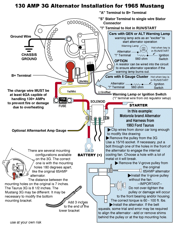
I've been searching so long (thanks Chicago) to get info on changing my Tuff Stuff 100 amp one wire alternator to a 3G. I'm still confused as to how to wire it since I only have the one wire. I have Dakota Digital for gauges so no amp gauge. Has someone done this conversion and can point me to info to help me with the changeover?

Thank you

Allen
 
#9 ·
Every 3G and 4G alternator has a stator plug. The stator wire seems stupid for 90s and up cars. It might be a holdover from the 2G alternator. I can't think of any cars with a 3G alternator that were not fuel injected. Certainly, the technology exists to have the wire integral with the alternator. Maybe there were trucks with an electric choke. It's probably a way to make millions of dollars.
 
#23 ·
The green red wire. Is that supposed to be used with a warning light (if you have one?) or does it need to be connected to a switched power source regardless for functional purposes?

Allen
 
#5 ·
I do find it interesting that the Painless diagram shows the red wire being connected to the battery while the diagram listed by Don P shows it connected to the solenoid. Does it matter? My current 1 wire harness is connected to the solenoid.

Allen
 
#7 ·
#8 ·
Don't forget to have an appropriately sized thick gauge wire. I used this one from PA performance for the 130 amp with a 200A fuse: Premium Short (9905)

They also have a dummy regulator and alternator splice in harness if you don't want to modify your harness 1G-3G Conversion (462802C)
 
  • Like
Reactions: DonP
#11 ·
#19 ·
The yellow "A" wire can run right over to the "BAT" terminal. If you're making up a new output wire then stick both the "A" wire and output wire in the same ring terminal.

MEGA Fuse? Why? When was the last time you saw an alternator dead short the output circuit?
 
#18 ·
I bought a 3G alternator conversion harness that had a ring terminal on the yellow wire so it could connect to the output terminal of the alternator. But I had a big 4 gauge terminal to connect to the same post. Stacking the little ring terminal and the big terminal was weak because it did not have full contact with the flange nut or the contact on the alternator depending on which way you stack them. So I extended the yellow wire a few inches and connected it to the solenoid post. It seems more secure to have the big wire terminal and a flange nut alone on a post. Same thing with the mega fuse. It seems more secure to have 2 small terminals on the battery side of the solenoid.
 
#20 ·
I just purchased my 3G alternator from AutoZone. Have clocked it so it’s in the right position. Now just waiting for my wiring harness from Summit Racing.

Allen
 
#24 ·
I'm leaning towards a runaway regulator (effectively full-field) blowing the fuse to protect the rest of the car, not the alternator. Just guessing, and I'm open to other theories as to why Ford used Mega fuses on 3Gs. 🤷‍♂️
That wouldn't happen. Yeah, the alternator may be putting out 16v but the current flowing through the fuse is only going to be what is consumed by the loads attached to the system.

The green red wire. Is that supposed to be used with a warning light (if you have one?) or does it need to be connected to a switched power source regardless for functional purposes?
Allen
The GRN/RED is the "exciter" and is connected to the 3G regulator's "I" terminal regardless of whether you have a warning lamp or an ammeter. In some installations using an ammeter, a 560 Ohm in-line resistor is needed in this circuit to induce a load sufficient to excite the alternator immediately.
 
#25 ·
That wouldn't happen. Yeah, the alternator may be putting out 16v but the current flowing through the fuse is only going to be what is consumed by the loads attached to the system.


The GRN/RED is the "exciter" and is connected to the 3G regulator's "I" terminal regardless of whether you have a warning lamp or an ammeter. In some installations using an ammeter, a 560 Ohm in-line resistor is needed in this circuit to induce a load sufficient to excite the alternator immediately.
I have Dakota Digital gauges and the voltmeter runs off of a ignition switched on wire under the dash. So I’m still confused. Do I need to connect the green red wire to a switched on power wire because I need to “switch on” the alternator? Can I attach the green red wire to any switched on wire in the engine compartment?

Allen
 
#34 ·
Or, if you want to keep the functionality of your ammeter....
Correct for the ammeter, but the diagram reroutes the sensing wire. To maintain full regulator function, the "A" YEL-WHT wire should go to the solenoid also, as it did originally ("A" YEL). It is a voltage/load sensing wire, to read the power junction between the battery and distribution, for voltage and load control. The 1Gs used it that way, as well as factory 3G, for best performance.
That wouldn't happen. Yeah, the alternator may be putting out 16v but the current flowing through the fuse is only going to be what is consumed by the loads attached to the system.
True, if the voltage does not change, but if you try it by full-fielding, the amps certainly do skyrocket. For example, the battery may be 'full', but if fed higher voltage, will accept all the amps that go with it. Even without testing, we see batteries boil, swell and puke from this effect. Higher voltage is higher amps, whether they want it or not. 🤷‍♂️
 
#47 ·
Correct for the ammeter, but the diagram reroutes the sensing wire. To maintain full regulator function, the "A" YEL-WHT wire should go to the solenoid also, as it did originally ("A" YEL). It is a voltage/load sensing wire, to read the power junction between the battery and distribution, for voltage and load control. The 1Gs used it that way, as well as factory 3G, for best performance.
The YELLOW wire isn't any "special wire". It's simply a connection to battery voltage. Voltage readings at the points indicated in the diagram, below, are all going to be the same differing only by the amount of voltage drop in the circuit path from the battery positive post to the regulator or alternator due to resistance in the conductor and connections which should not exceed 0.1vDC.

Image
 
#37 ·
Interesting. I've just been running one large cable. I also extend the "A" terminal wire to where the solenoid is. Someone once told me that done that way it "senses" system voltage better than if just short looped to the alternator B+ terminal. Beyond me to prove that one way or the other though.
 
#40 ·
They are all self-exciting, assuming no power feed or dash light connection (where the original exciter signal comes-from). Self-exciting simply means it uses residual magnetism to get the voltage going, and then it is self-building and self-sustaining. Remember the old generator magnetizing routine to get them working again? Same effect.

This is true even with a stock regulator with disconnected signal wire, but is the source of the "rev it to get it charging" anomaly that they have to one degree or another, and also affected by time and loss of magnetism since last run. So if recently run, it may begin charging immediately, or only after revving above an rpm that permits the cycle to begin.

The linked regulator may be modified to trigger at a lower voltage signal, but still lacks the functions like any 1-wire alternator. Also note a "14.6V max" internal setting they mention means it would not be suitable for colder weather or max-amp operation, where factory regulators can get to 15.5V under specific conditions requiring it. Ever notice your stock after-start voltage being oddly high? That's your regulator trying to quickly recharge your battery after cranking sucked it down. Again, the broken record - pros and cons to everything. Know what they are to get what you need.

PS: the review comment of the old regulator "drop and rise of voltage at lower RPM's" is a typical symptom of deleting or jumping the YEL-WHT sensing wire to the output instead of the solenoid stud. "True" 1-wire regulators combine the lack of sensing wire with limited or damped voltage range to solve this issue, but you can imagine the downsides to that for many applications. The sense wire is trying to tell the regulator what the system needs, or we can effectively put duct tape on this mouth so it can't speak. Easier to ignore what it's trying to say that way and voltage is 'stable', whether correct or not. ;)

Last words and done - "true" 1-wire regulators are computer-controlled. To get all the features and benefits, we need either a 1-wire designed for a controller (gets all the info the other wires used to), or use more wires to the alternator. If you have an application that does not require the typical features of a multi-wire or computer-controlled system, then run whatever you like that gets what you need. Do your thing. :cool:
 
#42 ·
From what I've read 1 wire regulators are microprocessor controlled. It constantly senses the battery voltage.
They are (as are stock regulators), but the micro-controller (µC) has the extra wires for voltage sensing. It can't read system loads and voltages unless it has a way to reach out there for it. The µC either needs a wire to the alternator if the µC is there, or gets it from the remote µC controller or ECM that has the extra wires. See what I'm saying? No wires anywhere for sensing, then no sensing, and no features or abilities it enables.

Here is one of my old first-gen micro-regulators for Ford-type alternators, but it still requires the extra wires to it, that it then controls the alternator with 1-wire. They have to be somewhere. 9V battery for size reference:
Image
 
#44 ·
to the OP, Any 3g Alternator brands did you end up going with?

I have 140 alt, wondering which is the best brand out there.

at least for me, I don't have that vintage regulator and my water pump is a reverse rotation (late 5.0) serpentine setup. Summitracing sells a ton of them and I think I found one that I think may fit my application.

 
#48 ·
This video shows the easy way to deal with the yellow wire. It may not be best, but it will work. You can lengthen the wire a few inches and connect it to the solenoid post. Takes no more than a few extra minutes. I don't like how they stack the big lug over the 2 small lugs. But it's a good marketing tool.

 
#50 ·
I finished the install today. Removed the voltage regulator (which wasn’t being used with the single wire alternator anyways). Connected the yellow wire to the B post with the red wire. Ran the ground wire from the back of the alternator to one of the screws holding the solenoid on. Although I’m sure all I had to do with the green red wire was to find a switched on power source, I ran it through the frame under the radiator and connected it to the green red wire from the voltage regulator harness.

Ground wire

Image

Image


Green red wire

Image


Image


Red wire

Image

Image


Image

Image


Allen
 

Attachments