Vintage Mustang Forums banner

5.0 EFI install complete

19K views 84 replies 24 participants last post by  Greg'66 5.0  
#1 · (Edited)
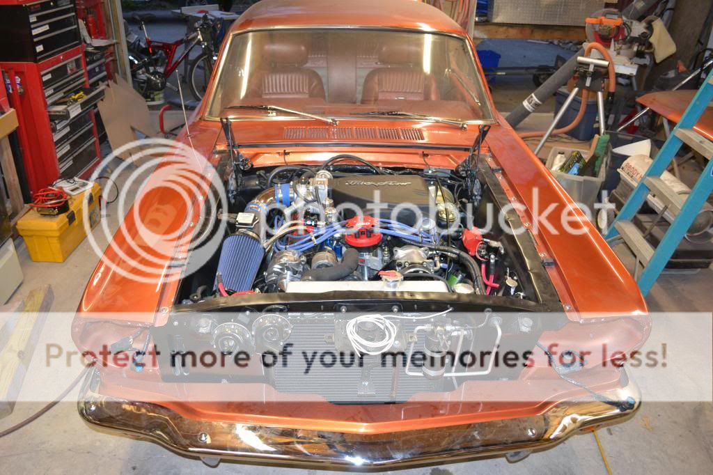
I think I have finally finished the installation of my 5.0 EFI engine conversion. It's been a long time in the making, but it's finally there. I'm hoping to have it running by the end of this weekend. I am so ready to drive this thing!

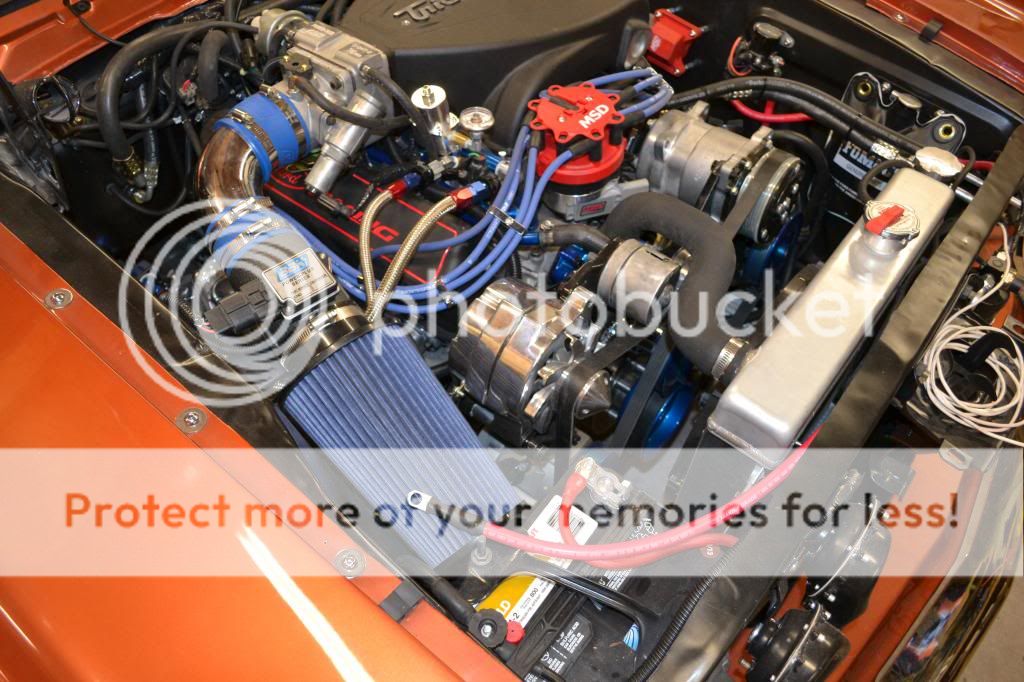
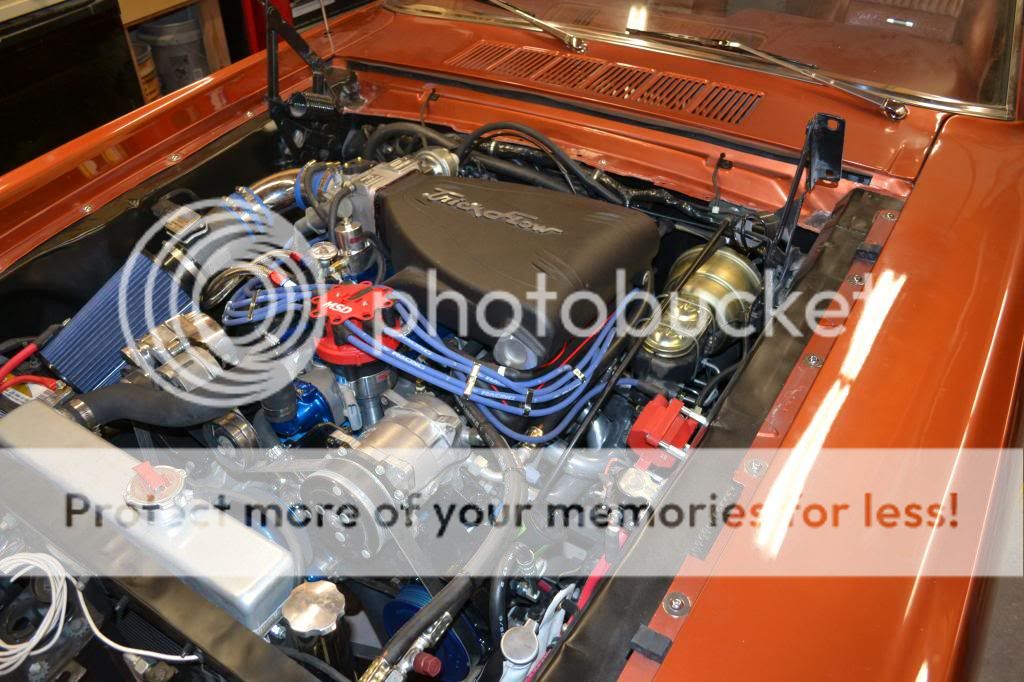
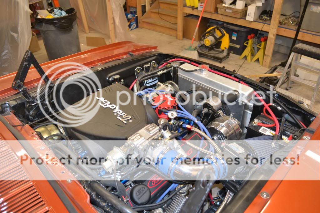
It's basically a complete Trick Flow package that should make around 350 HP. Overall it fits very well. I had to cut a few inches off the intake elbow so that the air filter would clear the battery. All I need to do now is put some gas in it, purge the air from the fuel lines, connect up the engine computer, and see if it will start. I am also doing something a little different here - I know everyone usually dumps the emissions control equipment since it's not required on a car this old, but I've got it all hooked up.


#3 ·
The solenoid is on the driver's side since I am using a complete 1986 Mustang wiring harness. I modified the fuel injection harness to be MAF compatible. In the later model Mustangs, the solenoid was on the driver's side so I went with that location since all the wiring for the harness was already laid out to that side. I would have had to lengthen all of the main feeds to the fuse panel to move the solenoid to the other side. In hindsight, I would have saved a lot of money on battery cables since a passenger side solenoid would have been near the battery and the starter, and the 10 or 12 AWG wire that feeds the fuse panel is a heck of a lot cheaper than the 1 AWG that makes my battery cables. Oh well, what's done is done!
 
#4 ·
Looks good... Congratulations...
How are you planning to purge the fuel lines? All's I did was put gas in the tank and then cycled of the key on / key off a few (3-4) times until gas was flowing back into the take via the return line. The only place there might be air is between the rail and injectors which I think is too short to worry about. Mine fired right up doing it this way.
 
#5 ·
The EFI harness has a diagnostic connector where you can read the codes. In that plug, there is a pin you can ground which will trigger the fuel pump relay and run the pump continuously. I am just going to do that instead of (cycling the key) and let the pump run to recirculate the fuel from the tank, through the rails, and back to the tank via the return line. Like you said, there will be a small amount of air at each injector, but it should clear pretty quickly when I start cranking the engine. I have a fuel pressure gauge connected to the regulator, so I'll be able to see when the pump is making pressure and I can use that opportunity to exercise the fuel pressure regulator with my handheld vacuum pump and adjust the fuel pressure if needed.
 
#9 ·
My plan is the same as yours. Between 300 and 350HP with Ford EFI, and emissions equipment as it came from the factory, minus the cats. I don't know what will happen in the future regarding vintage cars as far as emissions go, but if they start tightening the regulations, all I'll have to do is add cats and go.

John
 
#10 ·
looks great Greg. Glad to see it coming together. I eliminated the emissions stuff on mine also, but would not have been opposed to leaving it. I think I would have needed a can opener to get one more thing in that engine compartment, though. I'm still not 100% road ready with mine, but I'm very close. Have to readjust the valves, change the transmission pan and gasket, and the water pump has decided it likes to leak around one of the bolts when its cold. A few other hiccups, but its close. I'm really glad to see your project progressing.
 
#12 ·
To answer a couple of questions:

I plan on making a startup video and posting it. Crossing my fingers for this weekend.

Fuel lines/Radiator: I tried to take some pictures of the fuel lines the other day, but even on jackstands the car is too close to the ground to get any good shots. I used hard line under the car - 1/2" stainless steel for the supply and 3/8" for the return. Overkill, yes, but it should work fine. There is a short piece of rubber fuel injection rated hose running from the pump to the filter since my pump has a non-removable hose barb on the outlet. The fuel lines run along the passenger side frame rail and the subframe connector that I have on that side. The fuel lines terminate in the engine compartment on the frame rail about where the firewall is. From there, I am running braided stainless/rubber lines to the engine. The radiator (part # 6550L) & fan/shroud (FS251, I think) are from Mustangs Unlimited. The radiator is a 5.0 conversion radiator (so that the lower connection is on the driver's side). I also have an adjustable temperature switch connected to control the fan. I have maybe 3/4" clearance from the water pump snout to the fan.

In addition to the emissions control equipment, I also have cats. The cats are very small and were part of a Bassani x-pipe that I cut and modified for my use. The cats are maybe 3.5" in diameter and 6" long.

The stock hood clears the intake with no problem - roughly 3/4" clearance. Since my shock towers are removed, I had plenty of room for everything along the sides of the engine. The biggest clearance problem I had was on the passenger side valve cover. If I would have used short EFI valve covers, there would have been no problems, but I liked the styling of the tall covers that I got. The product description clearly stated that modification was necessary for EFI engines. The modification is required to clear the throttle linkage. If you look closely at the back of the passenger side valve cover, you can see a big chunk removed around the throttle cable.
 
#14 ·
Not going to use one. I don't have shock towers so there is nothing to mount to, other than the fender aprons. I think the upper intake manifold would get in the way, even if I used tubing and heim joints. I also don't need a Monte Carlo bar between the fenders since I have a big suspension crossmember welded in.
 
#16 · (Edited)
Nothing special on the fuel system. I am using a 1970 tank so that I get another 6 gallons of capacity. The pickup is just a plain old 1970 pickup. A rubber line runs from the pickup to the pump suction, and the pump mounted low enough outside the tank that it should self-prime as long as the tank is at least 1/4 full. The tank had a 1/4" NPT drain plug, so I removed the pipe plug and used the drain hole for the return line.

Not going to worry about the pickup running dry. It will be an occasional driver, so it's not likely that the tank will see low levels very often. I think the pump will keep suction as long as I have at least a 1/4 tank.

This picture isn't the greatest, but it shows what I did. The return line is the stainless line running to the blue fitting in the drain hole. The pump is also visible. The return line is 3/8" stainless line with a -6 AN fitting on the end. The elbow fitting is -6 AN male on one end and 1/4" NPT on the other.
 
#32 ·
If you need the Ron Morris pickup I have a brand new in the box one. I changed my mind and went with the in tank fuel pump.
 
#20 ·
Since I am running all of the emissions equipment, the tank is vented through a separate line to a charcoal canister in the engine compartment. I drilled a hole in the filler pipe for the vent line.

I don't see how pressure would be built in the tank by the return line. The pump is pulling a suction on the tank, so the fuel being returned to the tank is being pumped back out to the engine, resulting in a no net change in pressure in the tank. Now if the car was parked outside on a hot day, the tank would probably heat up a bit, causing the gas inside to expand a bit and also vaporize and pressurize the tank a bit.
 
#22 ·
I had a issue once the tank was full it was leaking fumes and a small amount of gas around the fuel hat that we installed into the top of the stock tank. I noticed a few times at the station when adding gas that the gas cap would have a lot of pressure when removing. I did like you and added a vent tube on the filler neck. I had a charcoal canister from one of my previous cars, but decide to install a 2 psi check valve on the vent tube and routed it underneath the car . Works great & no gas fumes in the shop when parked. Very nice work,and beautiful car also.
 
#21 ·
Nice and clean set up
 
#23 ·
Looks great!!! I see the Modern Driveline Clutch cable setup and I would love to know how that feels for you when you get it on the road. I had that clutch and it was way to hard to use and i went with their Hydraulic setup and its 10 times better for me. Wonder if its my setup or not.
 
#25 ·
Looks fabulous

Mine was done when I got it

Had good parts,rebuilt 1990 5.0, RJM harness. Stainless Tri Ys. But not a pretty install

Wiring was ugly, this was mostly the air conditioning and engine relays.

The tank was a fuel safe and gave a heavy petrol smell

I changed the tank to a drop in "tanks" unit and had the wiring cleaned up a ton

Still probably does not look as good as yours :)

How do you figure the HP at 350? Is the trick flow kit that strong? That intake looks great. I'd be happy if mine made 250. It's a stock rebuild with GT40 intake and the Tri Y's. had I built it I would have went 306 or 347 as it was down to the bare block.

Excited to hear how it runs

Peter
 
#26 ·
The 350 HP figure comes from Trick Flow. They have a dyno tested package that puts out that much power. I did not buy the entire pckage, but I bought components from the package - namely the heads, intake, and cam since those 3 make the biggest difference. I am running 30 lb/hr injectors and a 75mm intake, so there should be enough air and fuel to feed it.

Trick Flow also says that some aftermarket tuning is required to get the full horsepower value. For now, I will be running a stock A9L program. Depending on the performance I get, I might look into the Quarterhorse EEC-IV tuner.
 
#27 ·
I would be interested to see what you do with a tune.. for comparison, I'm running a 331 stroker, the same T/F heads and cam (stage 2), but with a Holley Systemax intake (mostly for clearance purposes), 30 lbs injectors, 70mm throttle body, a 90mm MAF and a crane ignition box. With a tune I'm hitting 360 rwhp.

-Shannon
 
#28 ·
Ran into what is hopefully a minor problem. I connected the battery and had some lights on the dash I wasn't expecting since they shouldn't have power when the key is off. My EEC power relay is being triggered and my ignition coil has power to it with the key off. I guess I accidentally spliced into a constant hot wire somewhere. I would imagine the engine will start, but I need to get this little problem figured out first or it might not be possible to shut off the engine without resorting to a drastic method such as disconnecting power to the coil. The hardest thing is that my main harness is nicely wrapped and firmly mounted behind the dash. It's rather hard to troubleshoot like that. I hope I don't have to go so far as taking the entire dash apart to get the harness out. I hope it's just something that's easy to find. I've pulled all the fuses from the fuse panel and still have power on that wire, so the circuit should not be getting backfed from another downstream of the fuses. It's got to be on the main supply coming in somewhere. I have a somewhat elaborate setup of 5 relays that I used to substitute for the ignition switch (my harness is a 1986 Mustang harness, and the ignition switch is much more complex on that year model). I am just using my 1966 ignition switch to trigger a relay for accessory, run, and start. The circuit is getting power with all the relays off and removed, so that also leads me to believe that my problem is on the incoming side.

Back to the garage to troubleshoot...:crybaby:
 
#29 ·
Thank goodness that didn't take long to figure out. It turns out that my one-wire alternator was the source of the crossed wires. There was originally a wire that ran from the alternator to the instrument cluster for the ammeter. Turns out there is a factory splice in the harness where this wire joins the circuit for the ignition coil and EEC power relay trigger. This wire was electrically isolated from the others in the old alternator, but with the single wire alternator I had all the wires connected to the same point. Since I'm not using that wire for anything, I simply clipped it and the problem went away. Just need to dress up that connection and rewrap about 2 feet of wiring harness that is fairly easy to get to.

My Navy Electronics Technician troubleshooting skills came in handy away from the job. All it took was a little half-splitting by unplugging one wiring harness connector to narrow the problem down to the dash wiring or the underhood wiring. I cannot express in words how happy I am to find out that it was not in the dash harness - that would have been a few days work to disassemble the dash to get the harness out.

Now back to prepping this thing for startup...